 EN
EN

AEM Electrolyser Technology Explained: Membranes, Catalysts and System Design
AEM electrolyser technology is attracting attention because it combines a compact solid-polymer separator with an alkaline operating environment. For engineering teams planning green-hydrogen capacity, the important question is not simply whether an AEM unit can split water. It is how the membrane, catalyst layers, flow fields, controls and balance of plant work together over time. This guide explains that system logic in practical terms.
How AEM Electrolyser Technology Moves Ions and Makes Hydrogen
An anion-exchange-membrane (AEM) electrolyser uses direct current to drive water-splitting reactions. At the cathode, water is reduced to hydrogen and hydroxide ions. The membrane selectively carries hydroxide ions toward the anode, where oxygen is formed. The membrane therefore performs several jobs at once: it provides ionic conduction, separates the product gases and creates the thin electrochemical boundary between the two electrodes.
This architecture differs from conventional liquid alkaline equipment, where a diaphragm separates larger electrolyte volumes, and from PEM systems, where protons move through an acidic membrane. In AEM electrolyser technology, the alkaline environment creates the opportunity to use lower-critical-material catalyst families. That opportunity is meaningful only when the complete membrane-electrode assembly (MEA) maintains low resistance, reliable water access and controlled gas crossover.
The Membrane: Conductivity, Selectivity and Chemical Stability
The AEM is not a passive separator. Its polymer backbone and fixed ionic groups must conduct hydroxide ions while resisting swelling, chemical attack and mechanical stress. A thinner membrane can reduce ohmic loss, but it can also make gas crossover, handling damage and pressure-differential management harder. A thicker membrane may improve robustness while adding resistance. Engineering teams should evaluate this trade-off at the intended current density, temperature, electrolyte condition and pressure profile—not from a conductivity value alone.
Membrane hydration also matters. Too little water at the interface can raise resistance and impair ion transport; uncontrolled water accumulation can obstruct gas pathways or create uneven local conditions. Because AEM electrolyser technology depends on interfaces, membrane selection should be reviewed together with ionomer compatibility, catalyst-layer porosity and compression hardware.
Catalysts and Catalyst Layers: More Than a Powder Choice
At the cathode, the hydrogen-evolution reaction must proceed quickly in an alkaline environment. At the anode, oxygen evolution is commonly the more demanding reaction at device level. Nickel-based and other non-platinum-group-metal approaches are often investigated for this setting, but a promising catalyst composition does not automatically produce a durable electrolyser.
The catalyst layer includes catalyst particles, anion-exchange ionomer, pores for liquid and gas movement, and contact with the membrane and porous transport layer. Each interface affects utilization. Insufficient ionomer can limit hydroxide transport; too much can restrict pores or alter wetting. Poor contact raises resistance. Local dry-out, bubbles or uneven compression can make a cell look like it has a catalyst problem when the underlying cause is transport or assembly.
| Design question | Why it matters | What to examine |
|---|---|---|
| Which catalyst is used? | Sets reaction activity and stability envelope. | Loading, support, dissolution risk and operating conditions. |
| How is the layer built? | Controls ionic, electronic and mass transport pathways. | Ionomer distribution, pore structure and coating uniformity. |
| How is it integrated? | Determines contact resistance and stress concentration. | Membrane interface, transport layer and compression window. |
From MEA to Stack: The System Design Logic
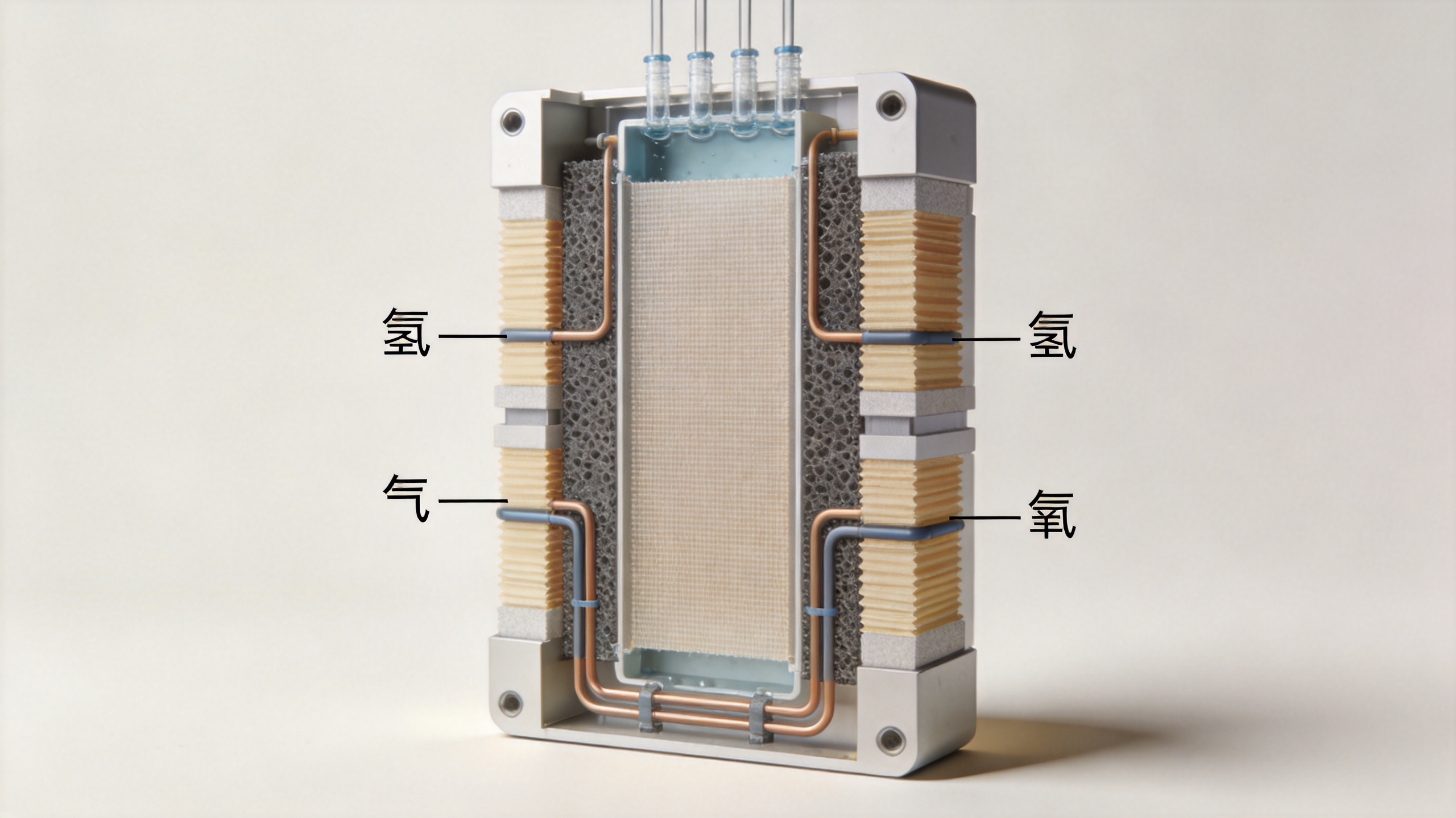
A practical AEM stack repeats cells through bipolar plates, flow fields, seals, current collectors and manifolds. Flow-field design must distribute water or electrolyte consistently, remove hydrogen and oxygen without excessive pressure drop, and avoid regions where bubbles remain trapped. Seals must withstand the chemical environment and thermal cycles while preserving the pressure boundary. Compression must be uniform enough to establish electrical contact without crushing porous layers or damaging the membrane.
Electrical design is equally important. A stack’s operating voltage is the sum of reversible voltage, reaction overpotentials, ionic resistance and contact losses. A good test plan separates these losses where possible, using polarization curves, impedance methods, differential-pressure tests and gas-quality monitoring. This enables engineers to identify whether a voltage rise comes from membrane resistance, catalyst-layer degradation, changing flow conditions or a mechanical contact issue.
Balance of Plant: Where Electrochemistry Meets Daily Operation
The stack cannot be assessed in isolation. Water-treatment quality, recirculation, pumps, heat rejection, sensors, power electronics, gas-liquid separation and safety logic affect the conditions seen by every cell. A system designed for variable renewable power should also define start-stop procedures, ramp limits and standby behavior. Frequent transients can change local hydration, temperatures and gas pressures, so they belong in durability validation rather than being treated as only a controls issue.
For projects that need modular hydrogen-production capacity, Hyto Energy’s 1MW-5MW system range can be a relevant starting point for discussing capacity configuration. The product page should be reviewed alongside confirmed project requirements; its title alone does not establish performance, certification or application-specific suitability.
A Practical Evaluation Checklist for Engineering Teams
- Define the duty cycle: Include target load range, ramping, downtime, ambient conditions and pressure requirements.
- Specify water and electrolyte conditions: Treat feed quality, recirculation chemistry and contaminant control as design inputs.
- Test component interactions: Review the membrane, ionomer, catalysts, transport layers and seals as an integrated MEA and cell.
- Measure gas management: Track crossover, separation performance, pressure balance and purge logic across operating points.
- Plan durability evidence: Ask for test conditions, not only headline results—especially thermal cycles, starts, stops and load changes.
- Connect stack data to balance-of-plant data: Monitor water, temperature, power quality and controls events when diagnosing degradation.
What AEM Electrolyser Technology Still Needs to Prove
AEM electrolysis has progressed quickly, yet performance, stability and scale-up remain active engineering challenges. The most credible development path is not a single breakthrough material. It is a stable set of interfaces: a membrane that stays conductive and selective, catalyst layers that remain connected and wetted, stack hardware that distributes fluids and loads evenly, and controls that keep the operating window disciplined.
For early-stage technical planning, start with the required hydrogen output and operating profile, then work backward through gas specifications, stack configuration, thermal management and MEAs. That approach makes it easier to compare AEM electrolyser technology with other electrolysis options on the conditions that matter to the project—not on isolated component claims.
AEM Electrolyser Technology Design Review Questions
Use this review list to turn a broad technology discussion into clear engineering questions. Each item should be assessed under the project’s real operating envelope.
- Can AEM electrolyser technology maintain its intended current density across the planned load range?
- Does AEM electrolyser technology have a membrane qualification plan for the selected water and electrolyte conditions?
- How will AEM electrolyser technology control membrane hydration during starts, stops and ramping?
- Which catalyst-layer interfaces set the performance limit in AEM electrolyser technology?
- Can AEM electrolyser technology maintain uniform compression across every active cell area?
- What gas-crossover monitoring is required for AEM electrolyser technology at each pressure condition?
- How does AEM electrolyser technology distribute feed water and remove bubbles from the flow field?
- Which seal materials are compatible with the chemical environment of AEM electrolyser technology?
- What diagnostic data will distinguish membrane resistance from contact losses in AEM electrolyser technology?
- How will the controls system protect AEM electrolyser technology during abnormal temperature or pressure events?
- What water-treatment specification is needed to support AEM electrolyser technology over the planned service interval?
- How do pumps, cooling and separators change the operating window for AEM electrolyser technology?
- What acceptance tests connect stack output with balance-of-plant behavior in AEM electrolyser technology?
- Which transient duty cycles should be included in durability validation for AEM electrolyser technology?
- What maintenance data will be collected to improve the next AEM electrolyser technology deployment?
- How will project teams compare AEM electrolyser technology with alternative electrolysis architectures on equivalent conditions?
- Which safety interlocks are essential when integrating AEM electrolyser technology into a hydrogen system?
- What evidence supports scale-up decisions for AEM electrolyser technology beyond a single-cell test?
- How will the project document component changes that affect AEM electrolyser technology performance?
- What operating data should trigger a root-cause review of AEM electrolyser technology?
- How will the team manage spare parts and service planning for AEM electrolyser technology?
- Which interface specifications must suppliers provide for AEM electrolyser technology integration?
- How can commissioning confirm that AEM electrolyser technology meets the agreed operating envelope?
- What documentation converts laboratory evidence into a bankable AEM electrolyser technology engineering decision?